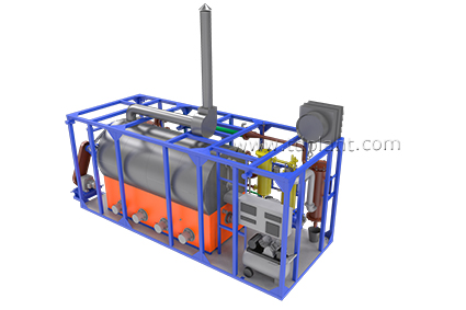
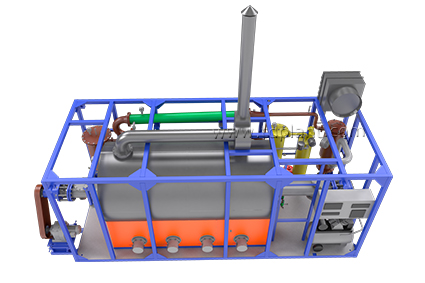
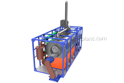
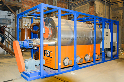
Continuous Thermal Decomposition Plant (TDP-2-200)
« Back to the list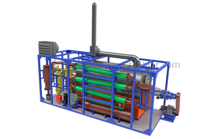


processing speed
qty of cycles of processing per day
tension
power consumption
INTENDED USE: Pyrolytic thermal decomposition of hydrocarbon waste with the recovery of pyrolysis gas, liquid fuel, and dry residue (carbon black).
WASTE TYPES: solid and liquid non-halogenous organic waste such as:
— Plastics, tires, rubber, polypropylenes,
— Oil sludge, oil-contaminated soils, drilling sludge and coal,
— Waste oils, tar, bitumen, kerosene, any type of solvents,
— Fuel oil residue, lubricating and heavy oils.
The process is based on low-temperature pyrolysis principle, involving the use of heat to thermally decompose hydrocarbon-based material in the condition of oxygen deficit.
Usage of the product derived from hydrocarbon-based raw materials:
- Dry residue is used as asphalt filler, in soil reclamation, construction or in production of coal bricks
- Heat of the process is recovered and used locally*
- Pyrolysis oil is used as:
— low grade fuel in boiler units
— fuel of higher quality, such as diesel**
- Syngas is used for the heating in the process
Usage of the product derived from brine-based raw materials:
- Distilled water is used as:
— drilling solution preparation
— drinking water ***
- Dry residue is used as asphalt filler and concrete additives
- Heat of the process is recovered and used locally*
* With an optional heat-exchanger (recuperator)
** With an optional rectification column
*** With an optional purification and mineralization systems
TDP-2-200 PROCESS DESCRIPTION
1. The source material is continuously fed into pyrolysis chamber:
- Paste and solid waste is fed by screw conveyor from the hopper.
- Liquid waste is fed from the receiver tank by the pump.
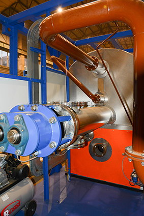
2. The pyrolysis chamber is heated to the operating temperature by the mixed fuel burner installed in furnace.
3. The pressure in the chamber is controlled by temperature rise rate.
4. Boiler fuel or diesel oil is used for the plant startup. Fuel is self-fed from fuel tank to the burner.
6. The beginning of the decomposition process is determined by the heat exchanger temperature rise to the set value.
7. After process stabilizing the main burner capacity is lowered and heating is carried out by booster burners operating on pyrolysis gas.

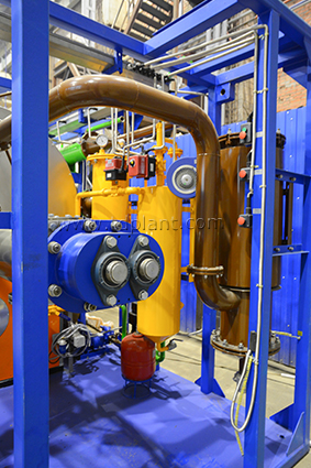
8. Vapor and gas mix from pyrolysis chamber is fed to the condensation system through gas filter.
10. The further cooling of the mixture is carried out in the heat exchanger by recirculation.
11. Water is cooled in air cooler or in chiller (depending on the operating conditions and feedstock composition).
12. Extension tank is installed in the line for the compensation of the volume fluctuations of chilled water.
13. Vapor-gas mix then enters separator where it is separated to liquid and gas phases.
=> LIQUID FUEL is drained to receiver tank and from there to the fuel tank or to the storage.
=> GAS is cleaned from sour components and is fed to the burners.
14. DRY RESIDUE is discharged by screw conveyor from the top of the reactor to the air tight hopper, where it cools and further to the storage bin, all the way without oxygen access.
Equipment

Thermal Decomposition Plant TDP-2-1000R (rotating reactor)

Continuous Thermal Decomposition Plant (TDP-2-2000)

Continuous Thermal Decomposition Plant (TDP-2-200)

Continuous Thermal Decomposition Plant (TDP-2-800)
All equipment How to purchaseNews

The upgraded TDP-2 continuous pyrolysis units continue to operate

Pyrolysis is the process of thermal decomposition of organic