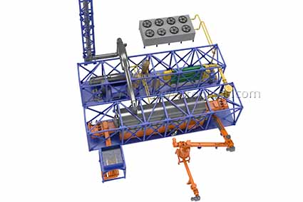
Continuous Thermal Decomposition Plant (TDP-2-2000)
« Back to the list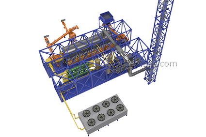

processing speed
qty of cycles of processing per day
tension
power consumption
INTENDED USE: Pyrolysis processing of hydrocarbon materials with the recovery of pyrolysis gas, liquid fuel, and biochar (carbon black).
WASTE TYPES: solid and liquid organic waste such as:
— Drilling waste
— Oil sludge
— Acid sludge
— Waste drilling muds and oil
— Waste rubber products, waste tires*
— Waste plastics, polypropylene bags, films*
______________
* shredder is required (not incl.)
ADDITIONAL FEATURES:
- Energy recovery. Thermal energy output capability.
- Electric power generation*
Capstone MicroTurbine => pyrolysis gas/oil electricity production
Electric energy output capability.
The amount of electricity generated is calculated in each case; depends on calorific value, type and volume of raw materials!
The option enables:
- Reduction the burden on facility’s electric power supply during a peak period
- Electricity provision to facility / field / locality
- Additional energy reserves in case of emergencies
- Usage of the process products (gas and oil) as an alternative energy source
______________
* when two Capstone turbines provided
TDP-2-2000 PROCESS DESCRIPTION
1. The source material is continuously fed into pyrolysis chamber:
- Paste and solid waste is fed by screw conveyor from the hopper.
- Liquid waste is fed from the receiver tank by the pump.
2. The pyrolysis chamber is heated to the operating temperature by the mixed fuel burner installed in furnace.
3. The pressure in the chamber is controlled by temperature rise rate.
4. Boiler fuel or diesel oil is used for the plant startup. Fuel is self-fed from fuel tank to the burner.
6. The beginning of the decomposition process is determined by the heat exchanger temperature rise to the set value.
 7. After process stabilizing the main burner capacity is lowered and heating is carried out by booster burners operating on pyrolysis gas.
8. Vapor and gas mix from pyrolysis chamber is fed to the condensation system through gas filter.
10. The further cooling of the mixture is carried out in the heat exchanger by recirculation.
11. Water is cooled in air cooler or in chiller (depending on the operating conditions and feedstock composition).
12. Extension tank is installed in the line for the compensation of the volume fluctuations of chilled water.
13. Vapor-gas mix then enters separator where it is separated to liquid and gas phases.
=> LIQUID FUEL is drained to receiver tank and from there to the fuel tank or to the storage.
=> GAS is cleaned from sour components and is fed to the burners.
14. DRY RESIDUE is discharged by screw conveyor from the top of the reactor to the air tight hopper, where it cools and further to the storage bin, all the way without oxygen access.
Autonomous power generation: pyrolysis gas/oil comes to the Capstone generators for the electricity production.
Dear visitors! This video displays the principle of the process, performance and technical features may vary.
Equipment

Thermal Decomposition Plant TDP-2-1000R (rotating reactor)

Continuous Thermal Decomposition Plant (TDP-2-2000)

Continuous Thermal Decomposition Plant (TDP-2-200)

Continuous Thermal Decomposition Plant (TDP-2-800)
All equipment How to purchaseNews

In early July, a Thermal Destruction Unit TDP-2-2000 was launched

The upgraded TDP-2 continuous pyrolysis units continue to operate